
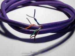
The 1-wire cabling of our modules is simply done via ethernet Cat5e cable.
This choice ensures a simpler/standard wiring and also an extremely effective cost per meter of the cable itself. The connector is an RJ45 with type B scheme as shown in the following figure
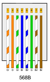 |
The cables are used as follows:
|
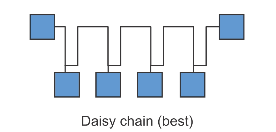
The right way to connect the modules is using a daisy chain scheme. Avoid stars because the cable and the modules are adapted to 100 Ohm impedance and using a star topology will change the impedance causing reflections of the signals thus risking to disrupt the communications. It is possible to realize a working star topology network but it is more art than science: the lines will not be adapted so propagation of the signal on the cable could change by simply adding or removing components or connections.
 |
|
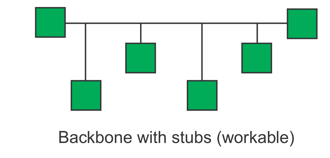
It is also possible to use stubs but they must be kept as short as possible (not more than 3-4 meters or 9-12 ft).
Have a look on this document to get a better idea on how to cable your bus: Guidelines for 1-wire reliable networks